Process and instrumentation diagram pdf Dubuc
TalkProcess and instrumentation diagram Wikipedia Merge proposal. Given that the pages of Process and instrumentation diagram and Piping and instrumentation diagram both contain the same example image, it seems that the distinctions between these two diagrams is trivial or small enough that both diagrams could be …
granulation process and instrumentation diagram
TalkProcess and instrumentation diagram Wikipedia. Piping and instrumentation diagram.pdf Piping and Instrumentation Diagram (P&ID) Sederhana Presentasi dan penjelasan P&ID pengontrolan pH secara kontinu sederhana, yaitu P&ID proses pembuatan disodium phospate menggunakan pH dan flow control., 23/05/2016 · P&ID's (piping &instrumentation diagrams), or Process and Control Flow Diagrams, are schematic representations of a process control system and used to illustrate the piping system, process ….
DHP’s Training Methodology DHP uses the consulting services of a Doctor of Education from Columbia University (Dr. Linda Paul) in the development of its online training courses. Overview. Process plants, such as refineries and petrochemical plants, are complex facilities consisting of equipment, piping systems, instruments, electrical …
To understand what is actually going on, let us first get to understand what the process whose piping and instrumentation diagrams is depicted above is all about. The heat exchanger is a process unit in which steam is used to heat up a liquid material. Piping and instrumentation diagram.pdf Piping and Instrumentation Diagram (P&ID) Sederhana Presentasi dan penjelasan P&ID pengontrolan pH secara kontinu sederhana, yaitu P&ID proses pembuatan disodium phospate menggunakan pH dan flow control.
A piping and instrumentation diagram, or P&ID, shows the piping and related components of a physical process flow. It’s most commonly used in the engineering field. … Process Flow Diagram (PFD) is a drawing which essentially captures the process flow for a processing plant. PFD is used to capture the main process equipment’s, main process stream, process/design conditions in these equipments and the basic process control scheme in a single drawing.
The process flow diagram typically identifies the major pieces of equipment, the flowpaths through the process, and the design operating conditions—that is, the flow rates, pressures, and tem- A conceptual process block diagram for a chemical process is shown in Figure 1–1. Notice that the inputs are classified as either manipulated or disturbance variables and the outputs are classified as measured or unmeasured in Figure 1–1a.
CBB1052 ENGINEERING GRAPHICS PROCESS FLOW DIAGRAM (PFD) & PROCESS AND INSTRUMENTATION DIAGRAM (P&ID) CHAPTER 9 WEEK 11 OBJECTIVES At the end of this lecture, students should be able to: tems, PLC documentation, and Pipe and Instrumentation Diagrams (P&ID). As in As in all engineering disciplines, the initial accuracy of these documents, and the regular
CBB1052 ENGINEERING GRAPHICS PROCESS FLOW DIAGRAM (PFD) & PROCESS AND INSTRUMENTATION DIAGRAM (P&ID) CHAPTER 9 WEEK 11 OBJECTIVES At the end of this lecture, students should be able to: BS 6739 Instrumentation in Process design and Practice DNV OS-D202 Instrument, control and safety systems EEMUA 178 A Design Guide for the Electrical Safety of Instruments, Instrument/Con-
for the Piping and Instrumentation Diagrams (P&IDs) and Utility Distribution Flow Diagrams (UDFDs) for process, offsite and utility plants. Namely, the purpose of this manual is to indicate in general terms, the extents of detailing, valving philosophy and instrumentation requirements of similar process designs. This Standard is also intended to establish uniform symbols for equipment, piping Overview. Process plants, such as refineries and petrochemical plants, are complex facilities consisting of equipment, piping systems, instruments, electrical …
Piping and instrumentation diagrams. P&IDs show how industrial process equipment is interconnected by a system of pipelines. P&ID schematics also show the instruments and valves that monitor and control the flow of materials through the pipelines. Process flow diagrams. PFDs show how industrial process equipment is interconnected by a system of pipelines. A PFD is more conceptual … CBB1052 ENGINEERING GRAPHICS PROCESS FLOW DIAGRAM (PFD) & PROCESS AND INSTRUMENTATION DIAGRAM (P&ID) CHAPTER 9 WEEK 11 OBJECTIVES At the end of this lecture, students should be able to:
To understand what is actually going on, let us first get to understand what the process whose piping and instrumentation diagrams is depicted above is all about. The heat exchanger is a process unit in which steam is used to heat up a liquid material. Process and Instrumentation Diagram. If you need create a Process and Instrumentation Diagram, it is convenient to design it in ConceptDraw DIAGRAM software which offers powerful Chemical and Process Engineering Solution from the Industrial Engineering Area.
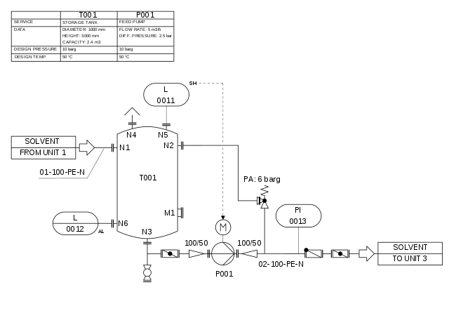
process flow diagrams (project standards and specifications) table of content scope 2 definitions and terminology 2 units 2 definition of process flow diagram (pfd) 3 purpose of pfd 3 contents of pfd 3 general drafting instructions 5 identification and numbering of equipment 8 description of equipment 9 description of instrumentation 11 material balance table 14 heat and material balance P&ID's shows all piping including physical sequences of branches, reducers, valves, equipment, instrumentation and control interlocks. The P&ID's are used to operate process systems.
Piping and Instrumentation Diagram PDF Free Download

How to Interpret Piping and Instrumentation Diagrams AIChE. A conceptual process block diagram for a chemical process is shown in Figure 1–1. Notice that the inputs are classified as either manipulated or disturbance variables and the outputs are classified as measured or unmeasured in Figure 1–1a., A piping and instrumentation diagram serves as an important reference that is useful at any stage of the process lifecycle. S Figure 2. Process fl ow diagrams illustrate major equipment and subsystems and the product fl ow.
Process and Instrumentation Diagrams YouTube. for the Piping and Instrumentation Diagrams (P&IDs) and Utility Distribution Flow Diagrams (UDFDs) for process, offsite and utility plants. Namely, the purpose of this manual is to indicate in general terms, the extents of detailing, valving philosophy and instrumentation requirements of similar process designs. This Standard is also intended to establish uniform symbols for equipment, piping, Process flow diagram (PFD) c. Material balance d. PFD symbols 3. Piping and instrumentation diagrams a. Piping and instrumentation diagram (P&ID) b. P&ID symbols c. Line numbering d. Valve numbering e. Equipment identification f. Abbreviations 4. Interpreting P&IDs - valves a. Valve types b. Valve identification.
Designing a Process Flowsheet coade.typepad.com

Piping and Instrumentation Diagrams OLC. CBB1052 ENGINEERING GRAPHICS PROCESS FLOW DIAGRAM (PFD) & PROCESS AND INSTRUMENTATION DIAGRAM (P&ID) CHAPTER 9 WEEK 11 OBJECTIVES At the end of this lecture, students should be able to: process flow diagrams (project standards and specifications) table of content scope 2 definitions and terminology 2 units 2 definition of process flow diagram (pfd) 3 purpose of pfd 3 contents of pfd 3 general drafting instructions 5 identification and numbering of equipment 8 description of equipment 9 description of instrumentation 11 material balance table 14 heat and material balance.

CBB1052 ENGINEERING GRAPHICS PROCESS FLOW DIAGRAM (PFD) & PROCESS AND INSTRUMENTATION DIAGRAM (P&ID) CHAPTER 9 WEEK 11 OBJECTIVES At the end of this lecture, students should be able to: A Definition of P&ID A piping and instrumentation diagram is a drawing in the process industry. A P&ID shows all piping, including the “physical sequence of branches, reducers, valves, equipment, instrumentation and control interlocks.”
Oct.1996 IPS-E-PR-230 4 1. SCOPE This Engineering Standard Specification covers the format and technical basis for the Piping and Instrumentation Diagrams (P&IDs) and Utility Distribution Flow Diagrams (UDFDs) for process, COMPLETE REVISION April 2008 P&ID Process Industry Practices Page 1 of 43 PIP PIC001 . Piping and Instrumentation Diagram Documentation Criteria
Piping and instrumentation diagram.pdf Piping and Instrumentation Diagram (P&ID) Sederhana Presentasi dan penjelasan P&ID pengontrolan pH secara kontinu sederhana, yaitu P&ID proses pembuatan disodium phospate menggunakan pH dan flow control. Piping and instrumentation diagram Wikipedia. A piping and instrumentation diagram (PID) is a detailed diagram in the process industry which shows the piping and vessels in the process flow, together with the instrumentation and control devices.
A piping and instrumentation diagram serves as an important reference that is useful at any stage of the process lifecycle. S Figure 2. Process fl ow diagrams illustrate major equipment and subsystems and the product fl ow BS 6739 Instrumentation in Process design and Practice DNV OS-D202 Instrument, control and safety systems EEMUA 178 A Design Guide for the Electrical Safety of Instruments, Instrument/Con-
Oct.1996 IPS-E-PR-230 4 1. SCOPE This Engineering Standard Specification covers the format and technical basis for the Piping and Instrumentation Diagrams (P&IDs) and Utility Distribution Flow Diagrams (UDFDs) for process, To understand what is actually going on, let us first get to understand what the process whose piping and instrumentation diagrams is depicted above is all about. The heat exchanger is a process unit in which steam is used to heat up a liquid material.
DHP’s Training Methodology DHP uses the consulting services of a Doctor of Education from Columbia University (Dr. Linda Paul) in the development of its online training courses. Merge proposal. Given that the pages of Process and instrumentation diagram and Piping and instrumentation diagram both contain the same example image, it seems that the distinctions between these two diagrams is trivial or small enough that both diagrams could be …
Klm technology group project engineering standard piping and instrumentation diagrams (p&id) (project standards and specifications) page 2 of 143.. COMPLETE REVISION April 2008 P&ID Process Industry Practices Page 1 of 43 PIP PIC001 . Piping and Instrumentation Diagram Documentation Criteria
Participation in the ISA standards-making process by an individual in no way constitutes endorsement by the employer of that individual, of ISA, or of any of the standards that ISA develops. The information contained in the preface, footnotes, and appendices is included for information only and is not a part of the standard. The instrumentation symbolism and identification techniques described Piping and instrumentation diagrams. P&IDs show how industrial process equipment is interconnected by a system of pipelines. P&ID schematics also show the instruments and valves that monitor and control the flow of materials through the pipelines. Process flow diagrams. PFDs show how industrial process equipment is interconnected by a system of pipelines. A PFD is more conceptual …
A conceptual process block diagram for a chemical process is shown in Figure 1–1. Notice that the inputs are classified as either manipulated or disturbance variables and the outputs are classified as measured or unmeasured in Figure 1–1a. Process diagrams can be broken down into two major categories: process flow diagrams (PFDs) and process and instrument drawings (P&IDs), sometimes called piping and instrumentation drawings.A flow diagram is a
Process flow diagram (PFD) c. Material balance d. PFD symbols 3. Piping and instrumentation diagrams a. Piping and instrumentation diagram (P&ID) b. P&ID symbols c. Line numbering d. Valve numbering e. Equipment identification f. Abbreviations 4. Interpreting P&IDs - valves a. Valve types b. Valve identification DHP’s Training Methodology DHP uses the consulting services of a Doctor of Education from Columbia University (Dr. Linda Paul) in the development of its online training courses.

Process and Instrumentation Diagram. If you need create a Process and Instrumentation Diagram, it is convenient to design it in ConceptDraw DIAGRAM software which offers powerful Chemical and Process Engineering Solution from the Industrial Engineering Area. With a bit of smoke, a few mirrors and a degree in hieroglyphics, anyone can learn to read a P&ID. Piping and Instrumentation Diagrams is a topic that can benefit process, project and design engineers, business developers, operators, safety, maintenance and even management.
Process and Instrumentation Diagrams YouTube

How to Interpret Piping and Instrumentation Diagrams AIChE. The Piping and Instrumentation Diagrams product provides customers with a complete set of tools to create, modify, analyze, and document their Piping and Instrumentation Diagrams (P&ID) designs. Specifically, this product provides you with the capability to create and manage logical designs of piping, Oct.1996 IPS-E-PR-230 4 1. SCOPE This Engineering Standard Specification covers the format and technical basis for the Piping and Instrumentation Diagrams (P&IDs) and Utility Distribution Flow Diagrams (UDFDs) for process,.
What is Process Flow Diagram (PFD) ? Instrumentation Tools
What is Piping and Instrumentation Diagram (P&ID)? Asset. A Definition of P&ID A piping and instrumentation diagram is a drawing in the process industry. A P&ID shows all piping, including the “physical sequence of branches, reducers, valves, equipment, instrumentation and control interlocks.”, Process and Instrumentation Diagram. If you need create a Process and Instrumentation Diagram, it is convenient to design it in ConceptDraw DIAGRAM software which offers powerful Chemical and Process Engineering Solution from the Industrial Engineering Area..
To understand what is actually going on, let us first get to understand what the process whose piping and instrumentation diagrams is depicted above is all about. The heat exchanger is a process unit in which steam is used to heat up a liquid material. A piping and instrumentation diagram serves as an important reference that is useful at any stage of the process lifecycle. S Figure 2. Process fl ow diagrams illustrate major equipment and subsystems and the product fl ow
Oct.1996 IPS-E-PR-230 4 1. SCOPE This Engineering Standard Specification covers the format and technical basis for the Piping and Instrumentation Diagrams (P&IDs) and Utility Distribution Flow Diagrams (UDFDs) for process, • Process Flow Diagram – PFD (simplified version of the P&ID) Piping and Instrumentation Diagrams or simply P&IDs are the “schematics” used in the field of instrumentation and control (Automation) The P&ID is used to by field techs, engineers, and operators to better understand the process and how the instrumentation is inter connected. Temperature Process. Using pictorial diagrams
17/05/2016В В· Process and Instrumentation Diagrams, also known as P&IDs, are basically maps meant to show process connections and equipment relationships pictorially. They are invaluable during the planning and With a bit of smoke, a few mirrors and a degree in hieroglyphics, anyone can learn to read a P&ID. Piping and Instrumentation Diagrams is a topic that can benefit process, project and design engineers, business developers, operators, safety, maintenance and even management.
P&ID's shows all piping including physical sequences of branches, reducers, valves, equipment, instrumentation and control interlocks. The P&ID's are used to operate process systems. Although instrumentation systems can be used in any continuous process, they may largely be categorized into two main divisions: process instrumentation and automation . Advances in computing have played a major role in the development and
piping and instrumentation diagrams (p&id) (project standards and specifications) table of content scope 2 references 2 definitions and terminology 3 symbols and abbreviations 3 units 3 general 4 minimum information to be shown on p&i diagrams 10 design criteria for preparation of p&i diagrams 25 criteria for utility flow diagrams 35 abbreviations / graphical symbols / identifications 37 Piping and instrumentation diagrams. P&IDs show how industrial process equipment is interconnected by a system of pipelines. P&ID schematics also show the instruments and valves that monitor and control the flow of materials through the pipelines. Process flow diagrams. PFDs show how industrial process equipment is interconnected by a system of pipelines. A PFD is more conceptual …
piping and instrumentation diagrams (p&id) (project standards and specifications) table of content scope 2 references 2 definitions and terminology 3 symbols and abbreviations 3 units 3 general 4 minimum information to be shown on p&i diagrams 10 design criteria for preparation of p&i diagrams 25 criteria for utility flow diagrams 35 abbreviations / graphical symbols / identifications 37 Oct.1996 IPS-E-PR-230 4 1. SCOPE This Engineering Standard Specification covers the format and technical basis for the Piping and Instrumentation Diagrams (P&IDs) and Utility Distribution Flow Diagrams (UDFDs) for process,
BS 6739 Instrumentation in Process design and Practice DNV OS-D202 Instrument, control and safety systems EEMUA 178 A Design Guide for the Electrical Safety of Instruments, Instrument/Con- COMPLETE REVISION April 2008 P&ID Process Industry Practices Page 1 of 43 PIP PIC001 . Piping and Instrumentation Diagram Documentation Criteria
With a bit of smoke, a few mirrors and a degree in hieroglyphics, anyone can learn to read a P&ID. Piping and Instrumentation Diagrams is a topic that can benefit process, project and design engineers, business developers, operators, safety, maintenance and even management. • Process Flow Diagram – PFD (simplified version of the P&ID) Piping and Instrumentation Diagrams or simply P&IDs are the “schematics” used in the field of instrumentation and control (Automation) The P&ID is used to by field techs, engineers, and operators to better understand the process and how the instrumentation is inter connected. Temperature Process. Using pictorial diagrams
tems, PLC documentation, and Pipe and Instrumentation Diagrams (P&ID). As in As in all engineering disciplines, the initial accuracy of these documents, and the regular A Definition of P&ID A piping and instrumentation diagram is a drawing in the process industry. A P&ID shows all piping, including the “physical sequence of branches, reducers, valves, equipment, instrumentation and control interlocks.”
BS 6739 Instrumentation in Process design and Practice DNV OS-D202 Instrument, control and safety systems EEMUA 178 A Design Guide for the Electrical Safety of Instruments, Instrument/Con- The Piping and Instrumentation Diagrams product provides customers with a complete set of tools to create, modify, analyze, and document their Piping and Instrumentation Diagrams (P&ID) designs. Specifically, this product provides you with the capability to create and manage logical designs of piping
What is Piping and Instrumentation Diagram (P&ID)? Asset

Piping and Instrumentation Diagram PDF Free Download. Piping and instrumentation diagram Wikipedia. A piping and instrumentation diagram (PID) is a detailed diagram in the process industry which shows the piping and vessels in the process flow, together with the instrumentation and control devices., Although instrumentation systems can be used in any continuous process, they may largely be categorized into two main divisions: process instrumentation and automation . Advances in computing have played a major role in the development and.
Basic Process Control The Piping & Instrumentation Diagram. COMPLETE REVISION April 2008 P&ID Process Industry Practices Page 1 of 43 PIP PIC001 . Piping and Instrumentation Diagram Documentation Criteria, The Piping and Instrumentation Diagrams product provides customers with a complete set of tools to create, modify, analyze, and document their Piping and Instrumentation Diagrams (P&ID) designs. Specifically, this product provides you with the capability to create and manage logical designs of piping.
Piping and Instrumentation Diagram PDF Free Download

Basic Knowledge about Piping and Instrumentation Diagram. 17/05/2016 · Process and Instrumentation Diagrams, also known as P&IDs, are basically maps meant to show process connections and equipment relationships pictorially. They are invaluable during the planning and DHP’s Training Methodology DHP uses the consulting services of a Doctor of Education from Columbia University (Dr. Linda Paul) in the development of its online training courses..

process flow diagrams (project standards and specifications) table of content scope 2 definitions and terminology 2 units 2 definition of process flow diagram (pfd) 3 purpose of pfd 3 contents of pfd 3 general drafting instructions 5 identification and numbering of equipment 8 description of equipment 9 description of instrumentation 11 material balance table 14 heat and material balance Piping and instrumentation diagram Wikipedia. A piping and instrumentation diagram (PID) is a detailed diagram in the process industry which shows the piping and vessels in the process flow, together with the instrumentation and control devices.
Although instrumentation systems can be used in any continuous process, they may largely be categorized into two main divisions: process instrumentation and automation . Advances in computing have played a major role in the development and Process Flow Diagram (PFD) is a drawing which essentially captures the process flow for a processing plant. PFD is used to capture the main process equipment’s, main process stream, process/design conditions in these equipments and the basic process control scheme in a single drawing.
tems, PLC documentation, and Pipe and Instrumentation Diagrams (P&ID). As in As in all engineering disciplines, the initial accuracy of these documents, and the regular Process Flow Diagram (PFD) is a drawing which essentially captures the process flow for a processing plant. PFD is used to capture the main process equipment’s, main process stream, process/design conditions in these equipments and the basic process control scheme in a single drawing.
COMPLETE REVISION April 2008 P&ID Process Industry Practices Page 1 of 43 PIP PIC001 . Piping and Instrumentation Diagram Documentation Criteria To understand what is actually going on, let us first get to understand what the process whose piping and instrumentation diagrams is depicted above is all about. The heat exchanger is a process unit in which steam is used to heat up a liquid material.
Although instrumentation systems can be used in any continuous process, they may largely be categorized into two main divisions: process instrumentation and automation . Advances in computing have played a major role in the development and COMPLETE REVISION April 2008 P&ID Process Industry Practices Page 1 of 43 PIP PIC001 . Piping and Instrumentation Diagram Documentation Criteria
Klm technology group project engineering standard piping and instrumentation diagrams (p&id) (project standards and specifications) page 2 of 143.. The process flow diagram typically identifies the major pieces of equipment, the flowpaths through the process, and the design operating conditions—that is, the flow rates, pressures, and tem-
Process flow diagram (PFD) c. Material balance d. PFD symbols 3. Piping and instrumentation diagrams a. Piping and instrumentation diagram (P&ID) b. P&ID symbols c. Line numbering d. Valve numbering e. Equipment identification f. Abbreviations 4. Interpreting P&IDs - valves a. Valve types b. Valve identification COMPLETE REVISION April 2008 Process Industry Practices P&ID PIP PIC001 Piping and Instrumentation Diagram Documentation Criteria Table of Contents
COMPLETE REVISION April 2008 Process Industry Practices P&ID PIP PIC001 Piping and Instrumentation Diagram Documentation Criteria Table of Contents Process Flow Diagram (PFD) is a drawing which essentially captures the process flow for a processing plant. PFD is used to capture the main process equipment’s, main process stream, process/design conditions in these equipments and the basic process control scheme in a single drawing.
A piping and instrumentation diagram, or P&ID, shows the piping and related components of a physical process flow. It’s most commonly used in the engineering field. … A conceptual process block diagram for a chemical process is shown in Figure 1–1. Notice that the inputs are classified as either manipulated or disturbance variables and the outputs are classified as measured or unmeasured in Figure 1–1a.
process flow diagrams (project standards and specifications) table of content scope 2 definitions and terminology 2 units 2 definition of process flow diagram (pfd) 3 purpose of pfd 3 contents of pfd 3 general drafting instructions 5 identification and numbering of equipment 8 description of equipment 9 description of instrumentation 11 material balance table 14 heat and material balance Overview. Process plants, such as refineries and petrochemical plants, are complex facilities consisting of equipment, piping systems, instruments, electrical …
Overview. Process plants, such as refineries and petrochemical plants, are complex facilities consisting of equipment, piping systems, instruments, electrical … • Process Flow Diagram – PFD (simplified version of the P&ID) Piping and Instrumentation Diagrams or simply P&IDs are the “schematics” used in the field of instrumentation and control (Automation) The P&ID is used to by field techs, engineers, and operators to better understand the process and how the instrumentation is inter connected. Temperature Process. Using pictorial diagrams