Water level sensor circuit pdf Jordan Harbour
Water Level Indicator Project IDC-Online Scouting for Water Level Sensor Wiring Diagram PDF Format Do you really need this book of Water Level Sensor Wiring Diagram PDF Format It takes me 81 hours just to get the right download link, and another 9 hours to validate it.
Training manual Capacitive and level sensors ifm.com
Water Level Sensor Circuit Wiring Diagrams. Column #27: Measure Water Level Without Getting Wet The Nuts and Volts of BASIC Stamps (Volume 1) • Page 275 The second task with the foil tape was hooking it up to my circuit., temperature sensor and humidity sensor also embedded as to relating the water level with the current temperature and humidity. The early data obtained by the SMS is used in determining the of flood impact toward the population by using.
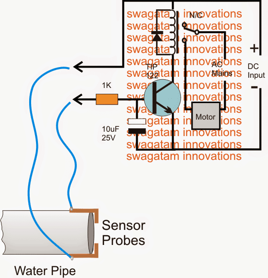
capacitance in an oscillator circuit. As a result, the oscillator begins oscillating. The trigger circuit reads the oscillator’s amplitude and when it reaches a specific level the output state of the sensor changes. As the target moves away from the sensor the oscillator’s amplitude decreases, switching the sensor output back to its original state. 55 Standard Target and Standard targets Introduction. In one of my previous articles, I discussed how to build a water level controller. There, we have seen how the proposed circuit is able to control the motor pump by switching it ON and OFF appropriately as per its settings and the water level of the tank to which it has been attached.
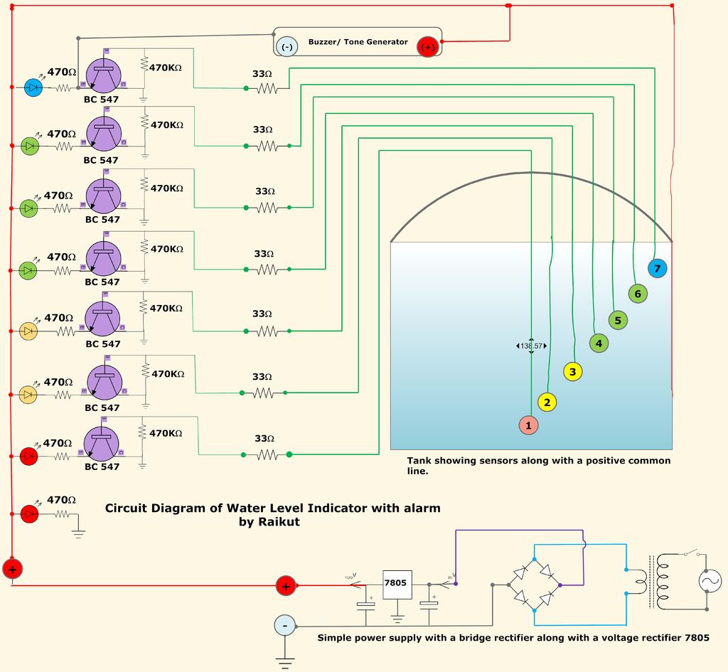
The Schematic is made with ExpressPCB which is a free PCB Layout Software you can download it here Than Download the PCB file and open and print it and make your PCB. This water sensor circuit is very sensitive to trigger and activate the audio visual alarm when wetness is sensed at its probes. This project is useful at homes to detect the water supply in the situations when the timing of water supply is not fixed.
Build A Water Level Indicator - Low-cost circuit lights a LED bargraph to indicate the level in a rainwater tank. This simple circuit lights a string of LEDs to quickly indicate the level in a rainwater tank. It's easy to build and can be powered from an AC or DC plugpack supply. Water Level Sensor Schematics Publisher Electronic Circuit. This simple water level sensor circuit monitors the presence of water in a certain location or container. The circuit sends an acoustic alarm when it senses a drop of water leak. It is very simple to build and it is made of a single IC and some passive components. Check out the water level indicator circuit too! The IC LM1801 is a low
Scouting for Water Level Sensor Wiring Diagram PDF Format Do you really need this book of Water Level Sensor Wiring Diagram PDF Format It takes me 81 hours just to get the right download link, and another 9 hours to validate it. Capacitive Sensors 2 • Surround this sensor with appropriate guard or shield electrodes to handle stray capacitance and crosstalk from other circuits
AquaPlumb ® - Water Level Sensors Buy Now The AquaPlumb ® series of liquid level sensor measure liquid level in tanks, reservoirs, and in the environment, without any moving parts. The sensing probe element consists of a special wire cable which is capable of accurately sensing the surface level of nearly any fluid, including water, salt water, and oils. Water Level Sensor Wiring Diagram PDF Format How to Value Your Water Level Sensor Wiring Diagram PDF Format eBook You’ve got written and compiled an Water Level Sensor Wiring Diagram PDF Format ebook. Now it’s a must to determine how a lot to charge for it. Discovering the proper worth is essential to the success of your product. If you cost too little Water Level Sensor …
Capacitive and level sensors 3 Contents 1 Introduction 5 1.1Proximity switches in industrial processes5 1.2Layout7 1.3On the contents8 2Basics9 2.1Capacitance9 The circuit shown in the presentation will sound an alarm endlessly until the circuit is switched off. The circuit shown at the top of this page is used to cut-off the …
Keep an eye on your outdoor water tank from the comfort of your own living room, up to 100m away. Installed at the top of your water tank, the transmitter unit measures the water level and temperature using an ultrasonic sensor. AquaPlumb В® - Water Level Sensors Buy Now The AquaPlumb В® series of liquid level sensor measure liquid level in tanks, reservoirs, and in the environment, without any moving parts. The sensing probe element consists of a special wire cable which is capable of accurately sensing the surface level of nearly any fluid, including water, salt water, and oils.
WL400 Water Level Sensor Submersible Pressure Transducer For Level & Pressure. Description . Global Water's WL400 Water Level Sensor submersible pressure transducer consists of a solid state pressure sensor encapsulated in a submersible stainless steel 13/16” diameter housing. The water level gauge uses a marine grade cable to connect the water pressure sensor to the monitoring device. … This is a tutorial to build a simple water level indicator alarm circuit using transistors. It indicates different levels of water and raise an alarm upon getting the tank full.
The liquid level must be higher than the reference sensor height in order to have liquid and temperature independent measurement system. SNOA927–December 2014 FDC1004: Basics of Capacitive Sensing and Applications 5 The probe is a sensor that extends downward from the fitting, with the tip positioned precisely at the level where the control should be activated. Warrick ® probes are available in a variety of materials to suit different liquids and a variety of lengths to fit different depth requirements.
Build A Water Level Indicator - Low-cost circuit lights a LED bargraph to indicate the level in a rainwater tank. This simple circuit lights a string of LEDs to quickly indicate the level in a rainwater tank. It's easy to build and can be powered from an AC or DC plugpack supply. capacitance in an oscillator circuit. As a result, the oscillator begins oscillating. The trigger circuit reads the oscillator’s amplitude and when it reaches a specific level the output state of the sensor changes. As the target moves away from the sensor the oscillator’s amplitude decreases, switching the sensor output back to its original state. 55 Standard Target and Standard targets
Water Level Indicator IJSER
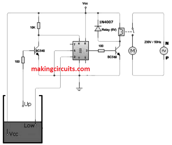
Water level sensor All About Circuits. The operation of water level controller works upon the fact that water conducts electricity due to the presence of minerals within it. So water can be used to open or close a circuit. As the water, A simple but very reliable and effective water level controller circuit diagram is shown here. The circuit uses 6 transistors, 1 NE555 timer IC, a relay and few passive components. The circuit is completely automatic which starts the pump motor when the water level in the over head tank goes below a preset level and switches OFF the pump when the water level in the over head tank goes ….
Water Level Sensor Testing ITRC. For any electrically conductive liquid level measurement, this single chip circuit is very compact and simple. This circuit is an ac excited fluid level sensor, which uses alternating current to provide biasing for the sensor probe to avoid electrolysis of the probes., Water level sensor circuit I have thought to use above diagram for our school project since we are about to celebrate our 50th school anniversary. I much greatly appreciate if you can recommend me nice & easy project to present in the educational exhibition..
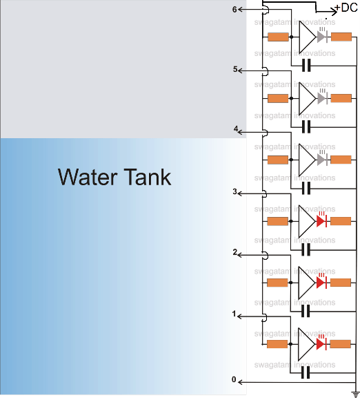
Water Level Indicator Circuit Using 555 And CD4049 – 6 LED

Water Level Indicator Using Arduino & Ultrasonic Sensor. This water sensor circuit is very sensitive to trigger and activate the audio visual alarm when wetness is sensed at its probes. This project is useful at homes to detect the water supply in the situations when the timing of water supply is not fixed. Water Level Indicator Project Circuit Diagram: This is the circuit diagram and description for water level indicator. A constant 5v power supply is given to the microcontroller and rest of the circuit ….
Level Sensors Contents Application notes.....2.03 - 2.07 Level Sensors Microwave meter Series MFP..2.08 - 2.12 The water content of an object or a liquid has a decisive influence on the switching point. A high humidity content increases the switching point considerably. Switching point sp The switching point or rated operating distance is a device parameter that does not take into Level Sensors Contents Application notes.....2.03 - 2.07 Level Sensors Microwave meter Series MFP..2.08 - 2.12 The water content of an object or a liquid has a decisive influence on the switching point. A high humidity content increases the switching point considerably. Switching point sp The switching point or rated operating distance is a device parameter that does not take into
The probe is a sensor that extends downward from the fitting, with the tip positioned precisely at the level where the control should be activated. Warrick ® probes are available in a variety of materials to suit different liquids and a variety of lengths to fit different depth requirements. and water level sensor. Abstract —In this paper we introduce the notion of water level monitoring and management within the context of electrical conductivity of the water. More specifically, we investigate the microcontroller based water level sensing and controlling in a wired and wireless environment. Water Level management approach would help in reducing the home power consumption and as
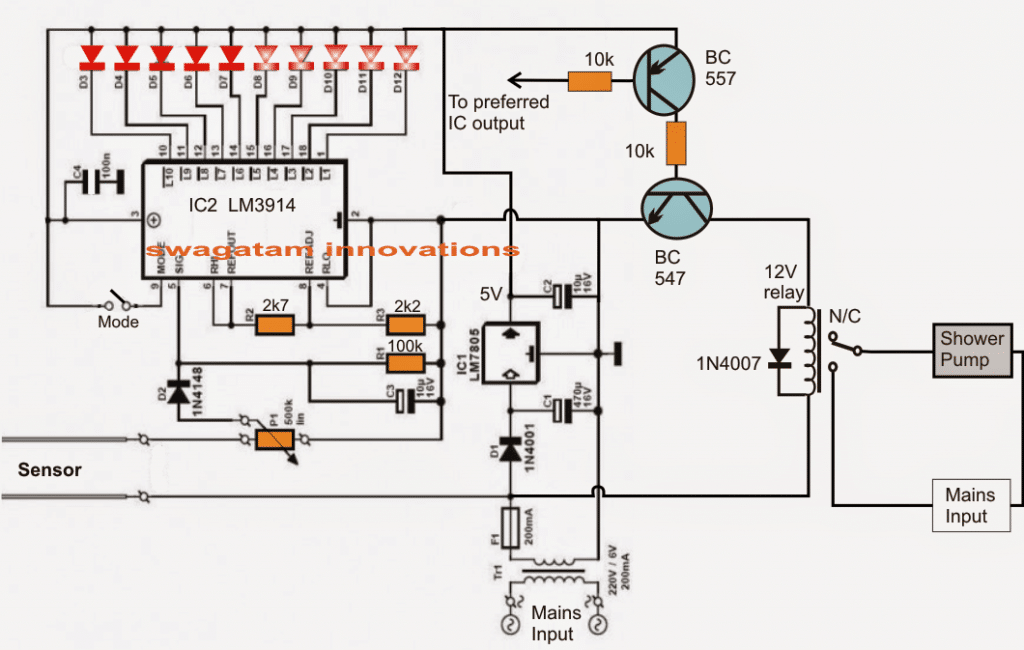
The variable resistor allows you to set the threshold level for the over-limit alarm. The red light should come on when you touch the sensor with your finger or get it wet with a drop of water. A simple but very reliable and effective water level controller circuit diagram is shown here. The circuit uses 6 transistors, 1 NE555 timer IC, a relay and few passive components. The circuit is completely automatic which starts the pump motor when the water level in the over head tank goes below a preset level and switches OFF the pump when the water level in the over head tank goes …
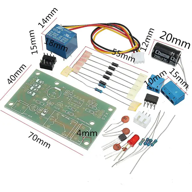
water level sensor circuits datasheet, cross reference, circuit and application notes in pdf format. Automatic turn off water pump on desired level + water level indicator/sensor PART NO. 2215988 This kit is used to learn how we can use simple cmos 4049 inverter to create latch circuit for turning ON and OFF water pump, sensor
Until the water level increases to the sensor point A, As a result, the sensor point A is connected to the test point C. The IC1 works and pulse signal generator. The IC1 works and pulse signal generator. Here’s a simple water level indicator for overhead tanks that uses three LEDs (LED1, LED2, and LED3) to indicate minimum, middle, and maximum water levels in the tank. The sensor probes comprise A, B, C, and D, where A is the common probe and B, C, and D are meant for sensing the minimum, middle
temperature sensor and humidity sensor also embedded as to relating the water level with the current temperature and humidity. The early data obtained by the SMS is used in determining the of flood impact toward the population by using Water Level Sensor Wiring Diagram PDF Format How to Value Your Water Level Sensor Wiring Diagram PDF Format eBook You’ve got written and compiled an Water Level Sensor Wiring Diagram PDF Format ebook. Now it’s a must to determine how a lot to charge for it. Discovering the proper worth is essential to the success of your product. If you cost too little Water Level Sensor …
The construction of this water level controller circuit is quite simple and may be easily completed by fixing and soldering the procured electronic components into a small piece of general purpose PCB. This simple water level sensor circuit monitors the presence of water in a certain location or container. The circuit sends an acoustic alarm when it senses a drop of water leak. It is very simple to build and it is made of a single IC and some passive components. Check out the
Water Level Indicator Project Circuit Diagram: This is the circuit diagram and description for water level indicator. A constant 5v power supply is given to the microcontroller and rest of the circuit … into water tanks in which the changes in the water level is sensed as input control signal used to command operations of air and water valve system to stabilize water flow rate at output.
WL400 Water Level Sensor Submersible Pressure Transducer For Level & Pressure. Description . Global Water's WL400 Water Level Sensor submersible pressure transducer consists of a solid state pressure sensor encapsulated in a submersible stainless steel 13/16” diameter housing. The water level gauge uses a marine grade cable to connect the water pressure sensor to the monitoring device. … Scouting for Water Level Sensor Wiring Diagram PDF Format Do you really need this book of Water Level Sensor Wiring Diagram PDF Format It takes me 81 hours just to get the right download link, and another 9 hours to validate it.
and water level sensor. Abstract —In this paper we introduce the notion of water level monitoring and management within the context of electrical conductivity of the water. More specifically, we investigate the microcontroller based water level sensing and controlling in a wired and wireless environment. Water Level management approach would help in reducing the home power consumption and as sensor is equipped with the optional temperature output circuit, To check the water level sensor calibration the following supplies are needed: 1 column of water (the closer the depth is to the maximum range of the sensor the better the calibration will be) 1 power supply 1 current meter Connecting wires as necessary Connect the sensor to the power supply and current meter in the following
2/01/2019В В· Hey! I am showing you to make a water level sensor using BC547b transistor on breadboard Including circuit diagram Components: BC547b transistor, breadboard, LED (x1), jumping wires, buzzer, 9v Capacitive and level sensors 3 Contents 1 Introduction 5 1.1Proximity switches in industrial processes5 1.2Layout7 1.3On the contents8 2Basics9 2.1Capacitance9
Ultrasonic Water Tank Level Meter with Thermo Sensor
A Low-Cost Water Sensor Circuit PracticingElectronics.com. Configured the sensor detect water levels, with can be combined with a electronic valve to control the water level. If interested there are few reference to help seek additional infomation. If interested there are few reference to help seek additional infomation., Water tank overflow liquid level sensor alarm circuit is a simple electronics project for school students. In the previous articles we had discussed about numeric water level indicator and water level controller circuit ,but those circuits are much complex and ….
for Automation EGE-Elektronik
Simple Water Detector Circuit ElectroSchematics.com. 28/07/2012В В· The idea is to make a water/air capacitor in which the amount of water dialectric is determine by the water level in the tank. Since the dialectric constant of water is about 80 times that of air, you get a pretty good capacitance change as the water level changes. You can then put this capacitor in a bridge circuit to get your readings., AquaPlumb В® - Water Level Sensors Buy Now The AquaPlumb В® series of liquid level sensor measure liquid level in tanks, reservoirs, and in the environment, without any moving parts. The sensing probe element consists of a special wire cable which is capable of accurately sensing the surface level of nearly any fluid, including water, salt water, and oils..
In this circuit, This circuit uses a liquid level sensor to measure the level of water in the water tank. The circuit produces the sound when the sensor senses a drop of a water leak. The circuit is very simple to build with the Microcontroller and also using water level sensor circuits datasheet, cross reference, circuit and application notes in pdf format.
28/07/2012В В· The idea is to make a water/air capacitor in which the amount of water dialectric is determine by the water level in the tank. Since the dialectric constant of water is about 80 times that of air, you get a pretty good capacitance change as the water level changes. You can then put this capacitor in a bridge circuit to get your readings. The construction of this water level controller circuit is quite simple and may be easily completed by fixing and soldering the procured electronic components into a small piece of general purpose PCB.
AquaPlumb В® - Water Level Sensors Buy Now The AquaPlumb В® series of liquid level sensor measure liquid level in tanks, reservoirs, and in the environment, without any moving parts. The sensing probe element consists of a special wire cable which is capable of accurately sensing the surface level of nearly any fluid, including water, salt water, and oils. The Schematic is made with ExpressPCB which is a free PCB Layout Software you can download it here Than Download the PCB file and open and print it and make your PCB.
water level sensor circuits datasheet, cross reference, circuit and application notes in pdf format. Water tank overflow liquid level sensor alarm circuit is a simple electronics project for school students. In the previous articles we had discussed about numeric water level indicator and water level controller circuit ,but those circuits are much complex and …
The Schematic is made with ExpressPCB which is a free PCB Layout Software you can download it here Than Download the PCB file and open and print it and make your PCB. The circuit shown in the presentation will sound an alarm endlessly until the circuit is switched off. The circuit shown at the top of this page is used to cut-off the …
The Schematic is made with ExpressPCB which is a free PCB Layout Software you can download it here Than Download the PCB file and open and print it and make your PCB. Capacitive and level sensors 3 Contents 1 Introduction 5 1.1Proximity switches in industrial processes5 1.2Layout7 1.3On the contents8 2Basics9 2.1Capacitance9
Water Level Indicator Description . This is the circuit diagram of a simple corrosion free water level indicator for home and industries. In fact, the level of any conductive non-corrosive liquids can be measured using this circuit. Water tank overflow liquid level sensor alarm circuit is a simple electronics project for school students. In the previous articles we had discussed about numeric water level indicator and water level controller circuit ,but those circuits are much complex and …
As the water continues to fill the tank. bilateral switch CMOS IC to indicate the water level through LEDs. When the water is full. the LEDs2 . The no. of levels of indication can be increased to 8 if 2 CD4066 ICs are used in a similar fashion.INTRODUCTION This circuit not only indicates the amount of water present in the overhead tank but also gives an alarm when the tank is full. The circuit In this project, we will build a liquid level sensor circuit with an arduino. If the board has water or another fluid covering all the wire, then it will output a maximum analog value reading. Since analog values read by an arduino range from 0 (lowest reading) to 1023 (highest reading), a board completely submerged with a liquid will have a reading of 1023 by an arduino. If the board is
The liquid level must be higher than the reference sensor height in order to have liquid and temperature independent measurement system. SNOA927–December 2014 FDC1004: Basics of Capacitive Sensing and Applications 5 You can use the simple sensor circuit in Figure 1 to remotely monitor the level of liquid water in a vessel such as a swimming pool. The LMC555 sensor oscillator provides an output-signal frequency that is a function of the water level.
Capacitive and level sensors 3 Contents 1 Introduction 5 1.1Proximity switches in industrial processes5 1.2Layout7 1.3On the contents8 2Basics9 2.1Capacitance9 Capacitive and level sensors 3 Contents 1 Introduction 5 1.1Proximity switches in industrial processes5 1.2Layout7 1.3On the contents8 2Basics9 2.1Capacitance9
OptiLevel Level Sensor Honeywell
Water Level Indicator IJSER. Introduction. In one of my previous articles, I discussed how to build a water level controller. There, we have seen how the proposed circuit is able to control the motor pump by switching it ON and OFF appropriately as per its settings and the water level of the tank to which it has been attached., 28/07/2012В В· The idea is to make a water/air capacitor in which the amount of water dialectric is determine by the water level in the tank. Since the dialectric constant of water is about 80 times that of air, you get a pretty good capacitance change as the water level changes. You can then put this capacitor in a bridge circuit to get your readings..
(PDF) AUTOMATIC WATER LEVEL INDICATOR ResearchGate
How to Build a Liquid Level Sensor Circuit with an Arduino. The variable resistor allows you to set the threshold level for the over-limit alarm. The red light should come on when you touch the sensor with your finger or get it wet with a drop of water. Rigid-flex circuit allows the sensors to be placed on various shaped surfaces Liquid height resolution <1mm Includes the environmental reference sensor to help compensate for environmental changes (temperature, humidity, stress on container, etc…) Developed to be paired with the FDC1004EVM and FDC1004EVM GUI for quick prototyping evaluation Home Appliances: refrigerators, coffee machines.

This water-level controller circuit makes this system automatic. It switches on the pump when the water level in the overhead tank goes low and switches it off as soon as the water level reaches a pre-determined level. It also prevents вЂdry run’ of the pump in case water level in underground tank goes below suction level. Water Level Controller can provide a solution to this problem. The operation of water level The operation of water level controller works upon the fact that water conducts electricity.
For any electrically conductive liquid level measurement, this single chip circuit is very compact and simple. This circuit is an ac excited fluid level sensor, which uses alternating current to provide biasing for the sensor probe to avoid electrolysis of the probes. Looking for Water Level Sensor Wiring Diagram Free Download Do you really need this ebook of Water Level Sensor Wiring Diagram Free Download It takes me 81 hours just to snag the right download link, and another 8 hours to validate it.
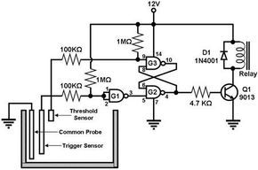
Rigid-flex circuit allows the sensors to be placed on various shaped surfaces Liquid height resolution <1mm Includes the environmental reference sensor to help compensate for environmental changes (temperature, humidity, stress on container, etc…) Developed to be paired with the FDC1004EVM and FDC1004EVM GUI for quick prototyping evaluation Home Appliances: refrigerators, coffee machines An electronic water-level alarm circuit is nothing but a circuit connected with an alarm to the above electronic water level circuit which is capable of alerting inmates of a home when the water level is high or low or exceeds higher limits, this type of electronic water level indicator circuit is used.
Catalog Datasheet MFG & Type PDF Document Tags; water level control circuit diagram. Abstract: circuit diagram water level sensor thermistor SCK 103 NTC NTC thermistor SCK 103 WATER LEVEL CONTROLLER water level sensor water level control water level sensor circuit diagram circuit diagram of process control of sequential timer using 3 relay MR321A OptiLevel Level Sensor The leading system for liquid level measurement in smaller storage tanks. Honeywell Enraf’s OptiLevel HLS 3010HF tank gauging system is the best choice for above and underground storage facilities. The OptiLevel tank gauging system can be used for all applications in petroleum and petrochemical installations. The state of the art HLS 3010HF level sensor and …
Water level sensor circuit I have thought to use above diagram for our school project since we are about to celebrate our 50th school anniversary. I much greatly appreciate if you can recommend me nice & easy project to present in the educational exhibition. temperature sensor and humidity sensor also embedded as to relating the water level with the current temperature and humidity. The early data obtained by the SMS is used in determining the of flood impact toward the population by using
6/02/2013 · Consider a circuit that is able to produce a luminosity signal to warn about one of the following events: 1)water level above 90 cm 2)water level below 30 cm Consider that you have a level sensor with signal conditioning that outputs a voltage proportional to: V(L)=1 + 10L (L-Level in metres) Water Level Sensor Wiring Diagram PDF Format How to Value Your Water Level Sensor Wiring Diagram PDF Format eBook You’ve got written and compiled an Water Level Sensor Wiring Diagram PDF Format ebook. Now it’s a must to determine how a lot to charge for it. Discovering the proper worth is essential to the success of your product. If you cost too little Water Level Sensor …
This is a tutorial to build a simple water level indicator alarm circuit using transistors. It indicates different levels of water and raise an alarm upon getting the tank full. sensor is equipped with the optional temperature output circuit, To check the water level sensor calibration the following supplies are needed: 1 column of water (the closer the depth is to the maximum range of the sensor the better the calibration will be) 1 power supply 1 current meter Connecting wires as necessary Connect the sensor to the power supply and current meter in the following
For any electrically conductive liquid level measurement, this single chip circuit is very compact and simple. This circuit is an ac excited fluid level sensor, which uses alternating current to provide biasing for the sensor probe to avoid electrolysis of the probes. Water Level Indicator Project Circuit Diagram: This is the circuit diagram and description for water level indicator. A constant 5v power supply is given to the microcontroller and rest of the circuit …
Keep an eye on your outdoor water tank from the comfort of your own living room, up to 100m away. Installed at the top of your water tank, the transmitter unit measures the water level and temperature using an ultrasonic sensor. and water level sensor. Abstract —In this paper we introduce the notion of water level monitoring and management within the context of electrical conductivity of the water. More specifically, we investigate the microcontroller based water level sensing and controlling in a wired and wireless environment. Water Level management approach would help in reducing the home power consumption and as
Looking for Water Level Sensor Wiring Diagram Free Download Do you really need this ebook of Water Level Sensor Wiring Diagram Free Download It takes me 81 hours just to snag the right download link, and another 8 hours to validate it. 2/01/2019В В· Hey! I am showing you to make a water level sensor using BC547b transistor on breadboard Including circuit diagram Components: BC547b transistor, breadboard, LED (x1), jumping wires, buzzer, 9v
Water tank overflow liquid level sensor alarm circuit is a simple electronics project for school students. In the previous articles we had discussed about numeric water level indicator and water level controller circuit ,but those circuits are much complex and … As the water continues to fill the tank. bilateral switch CMOS IC to indicate the water level through LEDs. When the water is full. the LEDs2 . The no. of levels of indication can be increased to 8 if 2 CD4066 ICs are used in a similar fashion.INTRODUCTION This circuit not only indicates the amount of water present in the overhead tank but also gives an alarm when the tank is full. The circuit