Torque equation of synchronous motor pdf Georgian Sands Beach
Torque Equation home.engineering.iastate.edu A Direct Torque Control of Interior Permanent Magnet Synchronous Motor for an Electric Vehicle-Design Analysis Total Harmonic Distortion of Stator Current
Torque Equation for Synchronous Machine Electrical Concepts
Torque Equation home.engineering.iastate.edu. Permanent Magnet Synchronous Motor Voltage Vector Control by Simulation Ambrish Pati Tripathi,Vikram Singh,Ankush Patidar Abstract— Proposed permanent magnet synchronous motor control based on MATLAB (PMSM) voltage vector control system model of simulation. And take the model for simulation experiment in Matlab/Simulink. The simulation result indicated that the …, synchronous motor has a synchronous reactance of 1.95 ohm/phase. Compute the max. Compute the max. torque in N-m which this motor can deliver if it is supplied from a constant frequency.
6 Synchronous motor 6.1 Principle of operation In order to understand the principle of operation of a synchronous motor, let us examine what happens if we connect the armature winding (laid out in the stator) of a 3-phase synchronous machine to a suitable balanced 3-phase source and the field winding to a D.C source of appropriate voltage. The current flowing through the field coils will A detailed analysis of the torque production in a permanent magnet synchronous motor drive with rectangular current excitation is presented. The effect of skewing is considered. The proposed method takes advantage of the knowledge of the flux density distribution in the air gap as a function of design parameters. The equations can be programmed easily and are very useful for parametric studies
Permanent magnet synchronous motors (PMS) are typically used for high-performance and high-efficiency motor drives. High-performance motor control is characterized by smooth rotation over the entire speed range of the motor, full torque control at zero … A synchronous electric motor is an AC motor in which, at steady state, the rotation of the shaft is synchronized with the frequency of the supply current; the rotation period is exactly equal to an integral number of AC cycles.
ABSTRACT This paper identifies a control method used to reduce torque ripple of a permanent magnet synchronous motor (PMSM) for an electric power steering (EPS) system. NVH (Noise Vibration Harshness) is important for safe and convenient 294 N. K. Kumari & et al.: Analysis of interior permanent magnet synchronous motor vector from a pre defined switching table. But the amount of ripples associated with the torque and flux are
In both cases when the load torque on a motor or the torque on a motor or the torque of the prime mover in a generator increases beyond a maximum, corresponding to cos ОІ = В±1, the machine cannot develop adequate torque and it loses synchronization. torque equation of blpm sine wave motor Ampere conductor density distribution Let the fig. 5.5 shows the ampere conductor density distribution in the air gap due to the
Higher efficiency higher torque multi-pole stator synchronous motors actually have multiple poles in the rotor. One-winding 12-pole synchronous motor. Rather than wind 12-coils for a 12-pole motor, wind a single coil with twelve interdigitated steel poles pieces as shown in Figure above . In the conventional direct torque control (DTC) of a permanent magnet synchronous motor (PMSM), hysteresis controllers areemployed toselect theproper voltage vector resulting inlarge torque ripples, and the inverse voltage vector, used in this system instead of the zero voltage vectors used in an induction motor, can accelerate the torque response but enlarges the torque ripples at the same
Maximum Torque • The power equation shows that the mechanical power increases with the torque angle – its maximum value is reached when δis 90° – the poles of the rotor are then midway between the north and south poles of the stator XS E E P 0 max = 3/28/00 Electromechanical Dynamics 8 Power and Torque • Example – 150 kW, 460 V, 1200 rpm, 60 Hz motor has a synchronous reactance of Synchronous Motors, Excitation & Control We Drive Industry Slide 1 Western Mining Electrical Association - May 2009 Synchronous Motors & Sync Excitation Systems
Induction Motors Torque equation; Torque equation In case of series motor the flux produced is directly proportional to the ar cur. Hence torque is directly proportional to the square of ar Torque-equation-of-an-induction-motor-eq-3 602 R. DOLEČEK, J. NOVÁK, O. ČERNÝ, TRACTION PERMANENT MAGNET SYNCHRONOUS MOTOR TORQUE CONTROL WITH… 2. Flux Weakening of PMSM The flux weakening control of a …
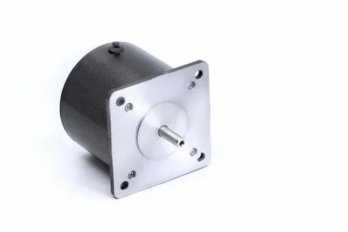
This catalog highlights the latest selection of high torque synchronous motors from Superior Electric. Our new line of NEMA size 42 high torque motors complements and extends the range of our size 23 and 34 high torque motors. These motors provide world-class performance, and represent the best value of any lineup ever offered by Superior Electric. They provide twice the torque (and in some HTS induction/synchronous machine (HTS-ISM) [11–16]. The basic structure of the machine is the same as that of the squirrel-cage induction motor, and the secondary windings are
ABSTRACT This paper identifies a control method used to reduce torque ripple of a permanent magnet synchronous motor (PMSM) for an electric power steering (EPS) system. NVH (Noise Vibration Harshness) is important for safe and convenient synchronous motor has a synchronous reactance of 1.95 ohm/phase. Compute the max. Compute the max. torque in N-m which this motor can deliver if it is supplied from a constant frequency
P. Záskalický et al. Torque Ripple Calculation of the Two-phase Permanent Magnet Synchronous Motor Supplied by a Triac Converter – 18 – inserted into the air-gap to protect the stator from water, and the whole rotor body In the conventional direct torque control (DTC) of a permanent magnet synchronous motor (PMSM), hysteresis controllers areemployed toselect theproper voltage vector resulting inlarge torque ripples, and the inverse voltage vector, used in this system instead of the zero voltage vectors used in an induction motor, can accelerate the torque response but enlarges the torque ripples at the same
Determination of Load Angle for Salient-pole Synchronous. 8 Speed control of Induction Machines We have seen the speed torque characteristic of the machine. In the stable region of operation in the motoring mode, the curve is rather steep and goes from zero torque at synchronous speed to the stall torque at a value of slip s = Л†s. Normally Л†s may be such that stall torque is about three times that of the rated operating torque of the machine, and, torque equation of blpm sine wave motor Ampere conductor density distribution Let the fig. 5.5 shows the ampere conductor density distribution in the air gap due to the.
Determination of Load Angle for Salient-pole Synchronous

Modeling and Simulation of Permanent Magnet Synchronous. 1 Model Predictive Direct Torque Control of Permanent Magnet Synchronous Motors Tobias Geyer, Member, IEEE, Giovanni A. Beccuti, Member, IEEE, Georgios Papafotiou, Member, IEEE and Manfred Morari, Fellow, IEEE, synchronous motors, especially those with permanent magnet rotors, are widely used for variable speed drives. If the stator excitation of a permanent magnet motor is controlled by.
Torque equation of three phase induction motor. In modern electrical drives, the energy saving starts with the careful generation of the electromagnetic torque, which involves the electrical motor and its current control., In modern electrical drives, the energy saving starts with the careful generation of the electromagnetic torque, which involves the electrical motor and its current control..
Torque equation of three phase induction motor

Analytical Method of Torque Calculation for Interior. Motor torque constant KT (lb-in/amp) Motor resistance Ra (ohms) Motor Brushless dc motors (BLDC) are 3 phase synchronous motors used in a configuration to be treated as dc drives. MOTOR RESISTANCE For the winding resistance use an ohmmeter. For a dc motor measure the resistance between the 2 armature wires. If it is a WYE connected BLDC motor, the resistance is the line-to … If a synchronous motor is subjected to instantaneous voltage sag, high torque peaks are develops that may pull motor out of step or damage the motor shaft or equip-.
294 N. K. Kumari & et al.: Analysis of interior permanent magnet synchronous motor vector from a pre defined switching table. But the amount of ripples associated with the torque and flux are simulation of a permanent magnet synchronous Motor (PMSM) drive system. The torque control of PMSM is achieved with the help of vector control, which is the widely accepted method. It provides independent control of torque and mutual flux. The switching signals for inverter are generated by two techniques to test their effect for superior performance of the drive. They are hysteresis and
1 Torque Equation (See section 4.9) Our goal is to combine the state-space voltage equations with the state-space torque equations. To achieve this, we need to do the following three things to the 8 Speed control of Induction Machines We have seen the speed torque characteristic of the machine. In the stable region of operation in the motoring mode, the curve is rather steep and goes from zero torque at synchronous speed to the stall torque at a value of slip s = Л†s. Normally Л†s may be such that stall torque is about three times that of the rated operating torque of the machine, and
Alternative Current motors, synchronous and asynchronous motors. These motors, when properly controlled and excited produce constant instantaneous torque . A. Objective of Problem . In what respect PMSM are better and whether motor be designed from few watts to mega watt with stable operation . B. Classification of Faults in PMSM . Replacing rotor field windings and pole structure … Simulation study of Conventional Control versus MTPA-Based for PMSM Control Abstract− in this paper, an analytical analysis for the permanent magnet synchronous motor (PMSM) control strategies will be provided and verified using the MATLAB program. A comparison between the conventional control (zero direct current) and the Maximum Torque per Ampere (MTPA) will be provided and verified on
Simulation study of Conventional Control versus MTPA-Based for PMSM Control Abstract− in this paper, an analytical analysis for the permanent magnet synchronous motor (PMSM) control strategies will be provided and verified using the MATLAB program. A comparison between the conventional control (zero direct current) and the Maximum Torque per Ampere (MTPA) will be provided and verified on PERMANENT MAGNET MOTOR TECHNOLOGY. PERMANENT MAGNET MOTOR TECHNOLOGY DESIGN AND APPLICATIONS THIRD EDITION. JACEK F. GIERAS Hamilton Sundstrand Aerospace, Rockford, IL, USA University of Technology and Life Sciences, Bydgoszcz, Poland PERMANENT MAGNET MOTOR TECHNOLOGY DESIGN AND APPLICATIONS THIRD EDITION CRC Press is …
Figure 5.36 shows a Synchronous Machine Torque Equation with a round rotor. The rotor is initially stationary with fixed north-south poles created by dc excitation. Let the 3-phase winding of the stator be connected to a 3-phase supply of fixed voltage V (line) and fixed frequency f (this is known as the infinite bus). As a result, 3-phase currents flow in the stator winding creating a synchronous motor using two level torque hysteresis controller. (Rahman et al., 1999) achieved the direct torque control by using a method based on obtaining the d …
A reluctance motor is a type of electric motor that induces non-permanent magnetic poles on the ferromagnetic rotor. The rotor does not have any windings. Torque is generated through the phenomenon of 294 N. K. Kumari & et al.: Analysis of interior permanent magnet synchronous motor vector from a pre defined switching table. But the amount of ripples associated with the torque and flux are
direct torque control for permanent magnet synchronous motor drive systems, PEDS2003, 692-697, 2003. [4] Lai Y S, Chan J H, A new approach todirect torque control of synchronous motor using two level torque hysteresis controller. (Rahman et al., 1999) achieved the direct torque control by using a method based on obtaining the d …
P. Záskalický et al. Torque Ripple Calculation of the Two-phase Permanent Magnet Synchronous Motor Supplied by a Triac Converter – 18 – inserted into the air-gap to protect the stator from water, and the whole rotor body A Direct Torque Control of Interior Permanent Magnet Synchronous Motor for an Electric Vehicle-Design Analysis Total Harmonic Distortion of Stator Current
equation of SM, similar to that of an induction motor. The electromagnetic torque of the synchronous motor, when the stator resistance R s is not negligible, is given ABSTRACT This paper identifies a control method used to reduce torque ripple of a permanent magnet synchronous motor (PMSM) for an electric power steering (EPS) system. NVH (Noise Vibration Harshness) is important for safe and convenient
In modern electrical drives, the energy saving starts with the careful generation of the electromagnetic torque, which involves the electrical motor and its current control. Induction Motors Torque equation; Torque equation In case of series motor the flux produced is directly proportional to the ar cur. Hence torque is directly proportional to the square of ar Torque-equation-of-an-induction-motor-eq-3
602 R. DOLEČEK, J. NOVÁK, O. ČERNÝ, TRACTION PERMANENT MAGNET SYNCHRONOUS MOTOR TORQUE CONTROL WITH… 2. Flux Weakening of PMSM The flux weakening control of a … magnet type servo motors, the per unit value of the synchronous inductance is typically in the range ld = 0.2−0.4. An adequate rotation speed range is often achieved by dimensioning the rated frequency of the machine to be sufficiently high. When employing embedded magnets, however, the inductances may be dimensioned so high that the rotation speed range can be expanded. Often when staying
Torque Equation of Synchronous Reluctance Motor YouTube

Torque equation of three phase induction motor. 8 Speed control of Induction Machines We have seen the speed torque characteristic of the machine. In the stable region of operation in the motoring mode, the curve is rather steep and goes from zero torque at synchronous speed to the stall torque at a value of slip s = ˆs. Normally ˆs may be such that stall torque is about three times that of the rated operating torque of the machine, and, available torque, the synchronous motor can slip one or more poles, causing a large transient disturbance. Speed control of the three-phase synchronous machine is ….
An Implementation of Direct Torque and Flux Control for
EE 340 Spring 2011 University of Nevada Las Vegas. simulation of a permanent magnet synchronous Motor (PMSM) drive system. The torque control of PMSM is achieved with the help of vector control, which is the widely accepted method. It provides independent control of torque and mutual flux. The switching signals for inverter are generated by two techniques to test their effect for superior performance of the drive. They are hysteresis and, torque equation of blpm sine wave motor Ampere conductor density distribution Let the fig. 5.5 shows the ampere conductor density distribution in the air gap due to the.
torque pulsations minimization in pm synchronous motor drive qian weizhe b. eng. a thesis submitted for the degree of master of engineering department of electrical & computer engineering torque pulsations minimization in pm synchronous motor drive qian weizhe b. eng. a thesis submitted for the degree of master of engineering department of electrical & computer engineering
Torque equation of BLPM sine wave motor 124 5 The synchronous reluctance motor has no synchronous starting torque and runs up from stand still by induction action. There is an auxiliary starting winding. This has increased the pull out torque, the power factor and the efficiency. Synchronous reluctance motor is designed for high power applications. It can broadly be classified … Xs1 = synchronous reactance, 2 f1Ls of the motor at the supply frequency f1. Equation 4.3.1 implies that the developed torque is proportional to the applied …
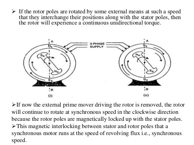
Analytical Method of Torque Calculation for Interior Permanent Magnet Synchronous Machines Seong Taek Lee 1 Student Member, IEEE 1University of Tennessee On achieving synchronous speed, magnetic locking occurs, and the synchronous motor continues to rotate even after removal of external mechanical means. Methods of Starting of Synchronous Motor Motor starting with an external prime Mover: Synchronous motors are mechanically coupled with another motor.
Maximum Torque • The power equation shows that the mechanical power increases with the torque angle – its maximum value is reached when δis 90° – the poles of the rotor are then midway between the north and south poles of the stator XS E E P 0 max = 3/28/00 Electromechanical Dynamics 8 Power and Torque • Example – 150 kW, 460 V, 1200 rpm, 60 Hz motor has a synchronous reactance of In the equation of torque, The rotor resistance, rotor inductive reactance and synchronous speed of induction motor remain constant. The supply voltage to the three phase induction motor is usually rated and remains constant, so the stator emf also remains the constant.
Torque equation in synchronous motor is directly proportional to the stator filed strength, rotor field strength and the sine of angle between them. Electrical Concepts Tricky but Easy Electrical Engineering! If a synchronous motor is subjected to instantaneous voltage sag, high torque peaks are develops that may pull motor out of step or damage the motor shaft or equip-
Motor torque constant KT (lb-in/amp) Motor resistance Ra (ohms) Motor Brushless dc motors (BLDC) are 3 phase synchronous motors used in a configuration to be treated as dc drives. MOTOR RESISTANCE For the winding resistance use an ohmmeter. For a dc motor measure the resistance between the 2 armature wires. If it is a WYE connected BLDC motor, the resistance is the line-to … synchronous motor has a synchronous reactance of 1.95 ohm/phase. Compute the max. Compute the max. torque in N-m which this motor can deliver if it is supplied from a constant frequency
P. Záskalický et al. Torque Ripple Calculation of the Two-phase Permanent Magnet Synchronous Motor Supplied by a Triac Converter – 18 – inserted into the air-gap to protect the stator from water, and the whole rotor body Abstract—A Synchronous motors and conventional induction motors are preferred as the most common drive for industrial and civil applications due to their simple construction and robustness. But they are not suitable when the application requires variable speed regulation. In such cases high torque, high efficiency, and simple controllability are often desired. Permanent Magnet Synchronous
synchronous motor in the rotor dq reference frame enables the developed torque and flux to be expressed in terms of certain currents which may be measured and controlled in closed loops in order to regulate the developed torque and flux of the machine. Abstract—A Synchronous motors and conventional induction motors are preferred as the most common drive for industrial and civil applications due to their simple construction and robustness. But they are not suitable when the application requires variable speed regulation. In such cases high torque, high efficiency, and simple controllability are often desired. Permanent Magnet Synchronous
Maximum Torque • The power equation shows that the mechanical power increases with the torque angle – its maximum value is reached when δis 90° – the poles of the rotor are then midway between the north and south poles of the stator XS E E P 0 max = 3/28/00 Electromechanical Dynamics 8 Power and Torque • Example – 150 kW, 460 V, 1200 rpm, 60 Hz motor has a synchronous reactance of Higher efficiency higher torque multi-pole stator synchronous motors actually have multiple poles in the rotor. One-winding 12-pole synchronous motor. Rather than wind 12-coils for a 12-pole motor, wind a single coil with twelve interdigitated steel poles pieces as shown in Figure above .
magnet type servo motors, the per unit value of the synchronous inductance is typically in the range ld = 0.2в€’0.4. An adequate rotation speed range is often achieved by dimensioning the rated frequency of the machine to be sufficiently high. When employing embedded magnets, however, the inductances may be dimensioned so high that the rotation speed range can be expanded. Often when staying On achieving synchronous speed, magnetic locking occurs, and the synchronous motor continues to rotate even after removal of external mechanical means. Methods of Starting of Synchronous Motor Motor starting with an external prime Mover: Synchronous motors are mechanically coupled with another motor.
Abstract—A Synchronous motors and conventional induction motors are preferred as the most common drive for industrial and civil applications due to their simple construction and robustness. But they are not suitable when the application requires variable speed regulation. In such cases high torque, high efficiency, and simple controllability are often desired. Permanent Magnet Synchronous Simulation study of Conventional Control versus MTPA-Based for PMSM Control Abstract− in this paper, an analytical analysis for the permanent magnet synchronous motor (PMSM) control strategies will be provided and verified using the MATLAB program. A comparison between the conventional control (zero direct current) and the Maximum Torque per Ampere (MTPA) will be provided and verified on
ECE 320 Energy Conversion and Power Electronics Chapter 7

Synchronous Machine Torque Equation EEEGUIDE. In both cases when the load torque on a motor or the torque on a motor or the torque of the prime mover in a generator increases beyond a maximum, corresponding to cos ОІ = В±1, the machine cannot develop adequate torque and it loses synchronization., The torque developed at the instant of starting of a motor is called as starting torque. Starting torque may be greater than running torque in some cases, or it may be lesser. Starting torque may be greater than running torque in some cases, or it may be lesser..
Synchronous Machine Torque Equation EEEGUIDE. A synchronous electric motor is an AC motor in which, at steady state, the rotation of the shaft is synchronized with the frequency of the supply current; the rotation period is exactly equal to an integral number of AC cycles., 8 Speed control of Induction Machines We have seen the speed torque characteristic of the machine. In the stable region of operation in the motoring mode, the curve is rather steep and goes from zero torque at synchronous speed to the stall torque at a value of slip s = Л†s. Normally Л†s may be such that stall torque is about three times that of the rated operating torque of the machine, and.
Mathematical Modeling and Simulation of Permanent Magnet

Torque Ripple Calculation of the Two-phase Permanent. Synchronous Motors, Excitation & Control We Drive Industry Slide 1 Western Mining Electrical Association - May 2009 Synchronous Motors & Sync Excitation Systems A synchronous electric motor is an AC motor in which, at steady state, the rotation of the shaft is synchronized with the frequency of the supply current; the rotation period is exactly equal to an integral number of AC cycles..
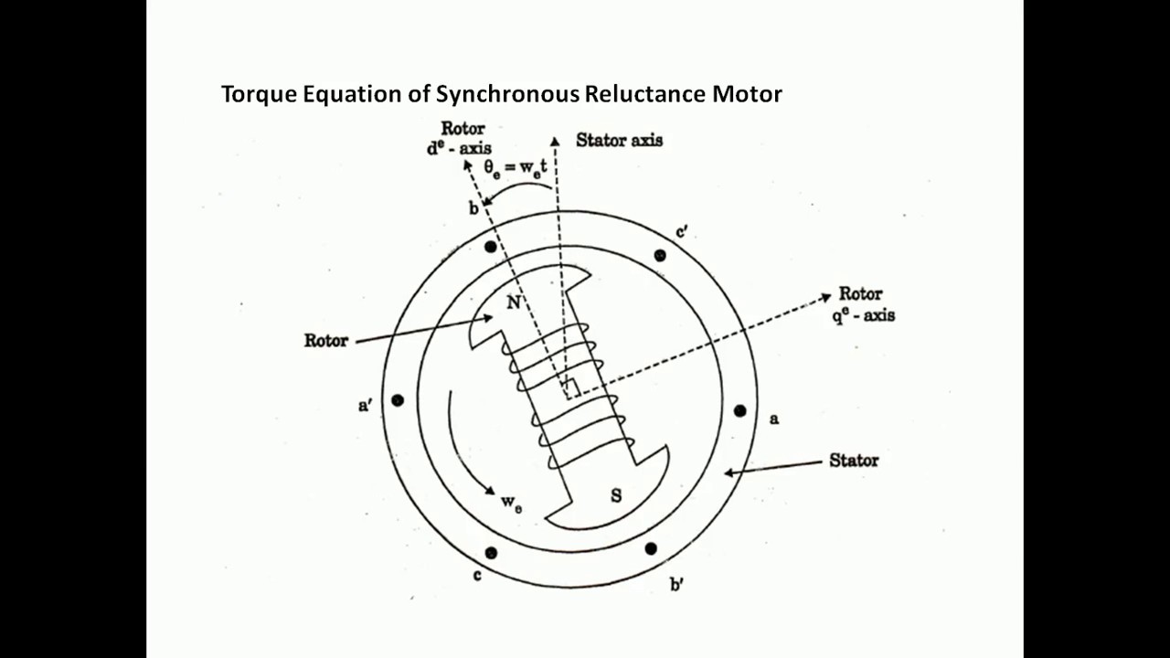
Sturtzer et al. proposed a torque equation for synchronous reluctance motors considering saturation effect [2]. Stumberger discussed a parameter measuring method of linear synchronous reluctance motors by using current, available torque, the synchronous motor can slip one or more poles, causing a large transient disturbance. Speed control of the three-phase synchronous machine is …
In the conventional direct torque control (DTC) of a permanent magnet synchronous motor (PMSM), hysteresis controllers areemployed toselect theproper voltage vector resulting inlarge torque ripples, and the inverse voltage vector, used in this system instead of the zero voltage vectors used in an induction motor, can accelerate the torque response but enlarges the torque ripples at the same Simulation study of Conventional Control versus MTPA-Based for PMSM Control Abstractв€’ in this paper, an analytical analysis for the permanent magnet synchronous motor (PMSM) control strategies will be provided and verified using the MATLAB program. A comparison between the conventional control (zero direct current) and the Maximum Torque per Ampere (MTPA) will be provided and verified on
Progress In Electromagnetics Research M, Vol. 39, 131–139, 2014 Torque Calculation in Interior Permanent Magnet Synchronous Machine Using Improved Lumped Parameter Models A detailed analysis of the torque production in a permanent magnet synchronous motor drive with rectangular current excitation is presented. The effect of skewing is considered. The proposed method takes advantage of the knowledge of the flux density distribution in the air gap as a function of design parameters. The equations can be programmed easily and are very useful for parametric studies
A Direct Torque Control of Interior Permanent Magnet Synchronous Motor for an Electric Vehicle-Design Analysis Total Harmonic Distortion of Stator Current Analytical Method of Torque Calculation for Interior Permanent Magnet Synchronous Machines Seong Taek Lee 1 Student Member, IEEE 1University of Tennessee
Motor torque constant KT (lb-in/amp) Motor resistance Ra (ohms) Motor Brushless dc motors (BLDC) are 3 phase synchronous motors used in a configuration to be treated as dc drives. MOTOR RESISTANCE For the winding resistance use an ohmmeter. For a dc motor measure the resistance between the 2 armature wires. If it is a WYE connected BLDC motor, the resistance is the line-to … A synchronous electric motor is an AC motor in which, at steady state, the rotation of the shaft is synchronized with the frequency of the supply current; the rotation period is exactly equal to an integral number of AC cycles.
ABSTRACT This paper identifies a control method used to reduce torque ripple of a permanent magnet synchronous motor (PMSM) for an electric power steering (EPS) system. NVH (Noise Vibration Harshness) is important for safe and convenient direct torque control for permanent magnet synchronous motor drive systems, PEDS2003, 692-697, 2003. [4] Lai Y S, Chan J H, A new approach todirect torque control of
A synchronous electric motor is an AC motor in which, at steady state, the rotation of the shaft is synchronized with the frequency of the supply current; the rotation period is exactly equal to an integral number of AC cycles. The torque developed at the instant of starting of a motor is called as starting torque. Starting torque may be greater than running torque in some cases, or it may be lesser. Starting torque may be greater than running torque in some cases, or it may be lesser.
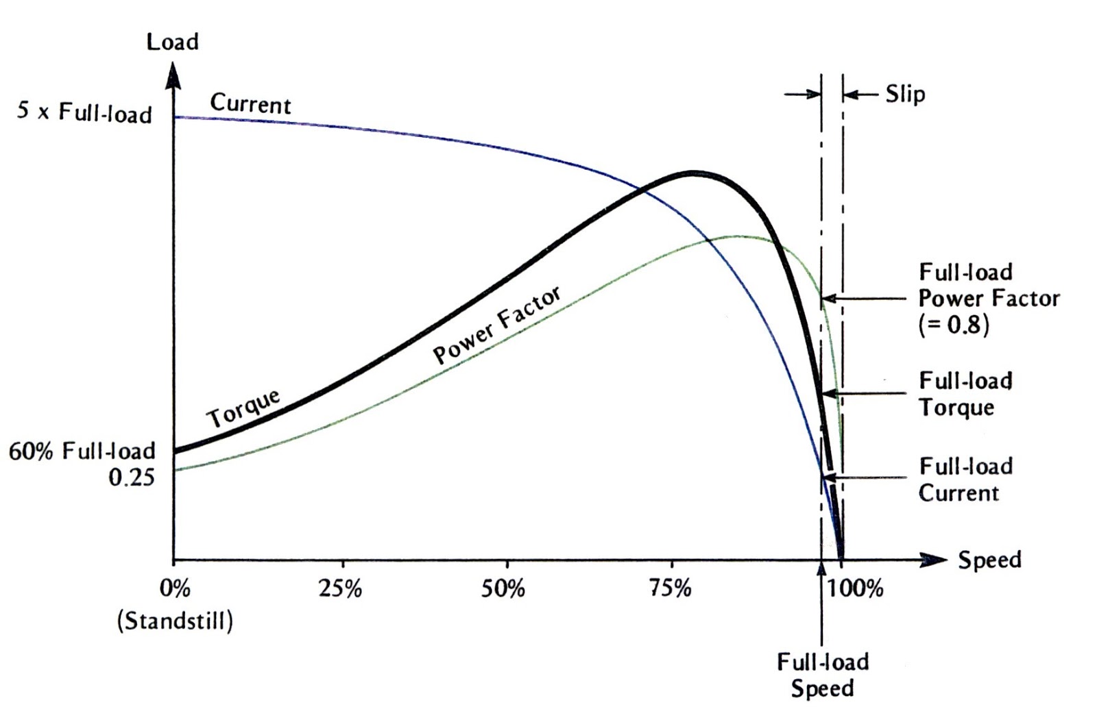
induction motor torque-speed characteristics Figure 6.12 a illustrates a squirrel-cage rotor of an induction motor that is operating at no load (near synchronous speed). The magnetization current I M flowing in the motor’s equivalent circuit (Fig. 6.7) creates the net magnetic field B net. Permanent magnet synchronous motors (PMS) are typically used for high-performance and high-efficiency motor drives. High-performance motor control is characterized by smooth rotation over the entire speed range of the motor, full torque control at zero …
simulation of a permanent magnet synchronous Motor (PMSM) drive system. The torque control of PMSM is achieved with the help of vector control, which is the widely accepted method. It provides independent control of torque and mutual flux. The switching signals for inverter are generated by two techniques to test their effect for superior performance of the drive. They are hysteresis and Analytical Method of Torque Calculation for Interior Permanent Magnet Synchronous Machines Seong Taek Lee 1 Student Member, IEEE 1University of Tennessee
torque pulsations minimization in pm synchronous motor drive qian weizhe b. eng. a thesis submitted for the degree of master of engineering department of electrical & computer engineering Figure 5.36 shows a Synchronous Machine Torque Equation with a round rotor. The rotor is initially stationary with fixed north-south poles created by dc excitation. Let the 3-phase winding of the stator be connected to a 3-phase supply of fixed voltage V (line) and fixed frequency f (this is known as the infinite bus). As a result, 3-phase currents flow in the stator winding creating a
Permanent Magnet Synchronous Motor Voltage Vector Control by Simulation Ambrish Pati Tripathi,Vikram Singh,Ankush Patidar Abstract— Proposed permanent magnet synchronous motor control based on MATLAB (PMSM) voltage vector control system model of simulation. And take the model for simulation experiment in Matlab/Simulink. The simulation result indicated that the … 602 R. DOLEČEK, J. NOVÁK, O. ČERNÝ, TRACTION PERMANENT MAGNET SYNCHRONOUS MOTOR TORQUE CONTROL WITH… 2. Flux Weakening of PMSM The flux weakening control of a …